Tech Tips for Drills in No-till
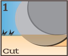
Cut residue and soil to create the furrow of the proper depth.
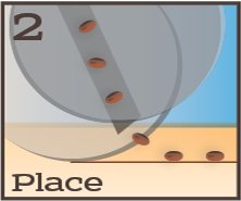
Place the seeds consistently into the bottom of the furrow.
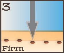
Firm the seeds by applying the right amount of pressure exactly where it is needed.
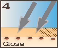
Close the furrow by chopping the sidewall, to prevent drying and allow good root exploration.
The concepts for drills are really no different from planters. Some drill designs cannot adequately perform Steps 1 – 4 described above because they are holdovers from the tillage era. In North America, one design that fulfills Steps 1, 2, 3, & 4 is the John Deere 750-type single-disc opener, including the 60-series (1560, 1860), 90-series (1890, 1990, 1895, 1690), and Pro-series*. Some comments to help them function:
Down-pressure
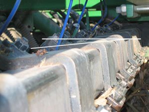
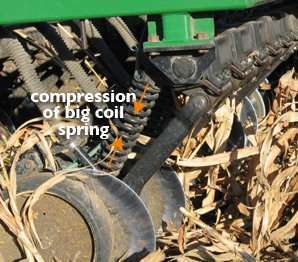
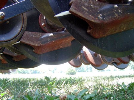
Use adequate down-pressure for the conditions. For the OEM spring setup, this often results in the rockshaft being tilted down in back (See photo in right-hand column) to gain enough compression on the big coil spring (up to two or three inches of compression is sometimes necessary). (Exapta also offers its UniForce system, that replaces the big coil spring with a hydraulic cylinder, to maintain pressure when the opener goes down in a slight depression—wheel track, etc.).
Additional ballast on the frame is often required, especially with the OEM spring setup. Increasing down-pressure without adequate ballast can result in the opener ‘rolling under’ or over-rotating, which actually decreases effective depth (very slight rolling under can be advantageous, however, since it orients the seed tube more vertically). Faster ground speeds will require more down-pressure and ballast.
If you’re only using one rank of openers (very common & desirable for seeding milo and certain other crops) and struggling to get enough down-pressure, be sure to use the front rank. It’s simply a matter of using the available ballast to the best advantage. When the down-pressure is cranked up, the drill frame will start to lift, but it always lifts the rear end first (due to the leverage of torquing the rockshaft against openers trailing behind the rockshaft)—so any extra weight is to the best mechanical advantage when it’s as far rearward as possible and still attached to the main frame. So, the rank that’s locked up becomes ballast, and you want this to be the back rank that’s carried, since all that weight is five foot behind the front rank.
Weights
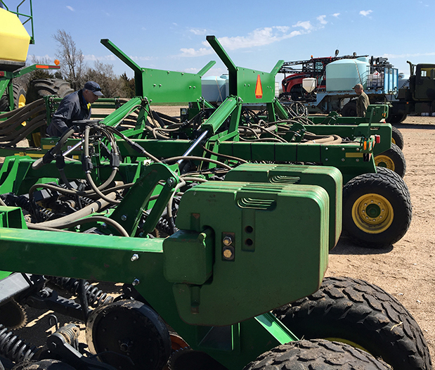
Deere did provide for additional suitcase weights in an intelligent location—on the box drills anyway—since they go between/above the rear transport wheels. On the air drill frames, Deere was more haphazard in locating them—again, the very best location is above/behind the rear rank (ideally, the weights would be over the transport wheels, for even greater leverage, rather than hanging off the toolbar just above the rockshaft). They should also be centered on each section as much as possible—the weights hanging way out on the ends of the wings cause the ends to dip unnecessarily. Weights at the front of the center section are poorly located to provide effective down-force transfer (although they might have purpose in loading the drawbar while pulling a tow-behind cart). The OEM weight brackets on the wings that are ahead of the rockshaft are rather ineffective.
We’ve seen all manner of weights added, ranging from old tractor wheel weights to concrete pillars and steel I-beams, and they all work just fine if they’re at the back of the drill. (Another reason you want the weight at the back is keep the load off the dolly wheels at the front, which tend to sink all too easily when you do encounter a soft spot.)
Once you have enough weight, you can easily run the hydraulic down-pressure way up into the red zone on the gauge. As a reminder, don’t use these gauges to compare with your neighbor—they’re not all the same as to the color markings, etc. All that’s really important is how much you’ve compressed the big coil spring on each opener. In really hard, dry conditions, you may need to compress that spring by 2.5 – 3 inches (which takes a lot of hydraulic pressure, and a lot of frame weight). This entails torquing the rockshaft so that it slopes downward in the back, by as much as 15 – 20 degrees (ignore the JD owner’s manual that says this rockshaft should be level—that’s not how the drill works at all: the only time it would be level is if you didn’t need much down-pressure, i.e., tilled or unusually mellow no-till conditions). Also, don’t fret too much about the Owner’s Manual warning about bearing failure when running in the red—a great many people have seeded tens of thousands of acres (per drill) this way, with the bearings having good longevity. Obviously, the high down-pressure puts more stress on everything (especially the torque tube itself), but the first task of a seeder is to get a good stand! Do what you need to do or wait for a rain.
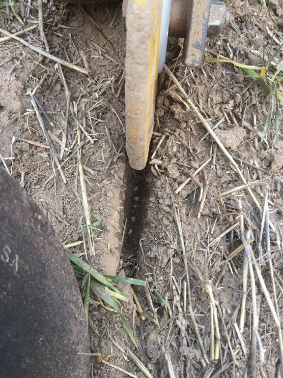
The gauge wheel should be firmly on the soil surface during seeding, which holds the sidewall together while the blade exits the soil. Also for this reason, reduced inner diameter tires (RID / CIH indented gauge tire) are strongly discouraged. Assessing whether the gauge wheel is remaining firmly on the surface requires examining a length of furrow to see that: 1) the furrow is being cut to a reasonably consistent depth, and 2) the sidewall is not blowing apart prematurely. This being said, there is a danger of excessive down-pressure also, which causes severe sidewall compaction. That said, the vast majority of drills we see in the field do not have enough down-pressure on the openers.
Opener blades should be replaced before the bevel is half gone for optimum performance (most of these blades have 5/8 – 3/4″ bevel new, so when this gets down to 5/16 – 3/8″, they’re maximum dullness). We prefer to use amount of bevel remaining, rather than diameter, to determine when to replace. Dull blades require more down-pressure to cut residue and slice the soil. Worn-down blades also accelerate wear on the seed boot & seed-boot attachment holes.
Because the outside edge of the boot hangs out past the blade (the boot is wider than the furrow cut), it is very difficult to push the boot into the soil. The lower edge of the boot generally should be just skimming the soil surface—the boot shouldn’t be forming the furrow, but instead keeps the loose duff layer (small pieces of decaying mulch) and some dust out of the furrow while the seeds drop into place. Worn blades decrease the effective depth, putting more wear on the boot, and also hindering the opener blade from reaching its depth (unless soils are quite mellow or tilled). If attempting to continue running worn blades, you may want to move the seed boot to the upper mounting hole (return it to the middle hole when installing new blades). Be sure to install new blades with the bevel away from the gauge wheel (worn blades are deceptive–what you think is a bevel sometimes is just advanced wear; so, don’t necessarily mimic what you think you see on the drill).
Seed Boots
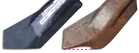
Seed boots should be inspected and maintained—the wear is not obvious from casual inspection. Compare a worn-out seed boot with a new one. When the bottom outside edge of the boot is no longer straight across, performance is compromised (the photos [above] show severe wear—performance was being affected much earlier). For improved wear life, upgrade to the chrome-alloy (JD’s “Extended Wear”) boots for 60- and 90-series drills, or tungsten-carbide boots for 50-series drills. Another option is to have the soft cast boots hard-surfaced (carefully) with nickel welding rod (after they’ve worn some, but before they wear through).
The seed-bounce flap on the back of the boot helps keep seeds in the furrow. JD finally improved theirs for the Pro-series drill (thicker material, tapered), but that type of flap (straight, semi-rigid) was already obsolete by then, with our more flexible Ninja flap with its unique forward-bend clearly setting the new standard for seed placement and longevity.
The 60-series drills had a poorly designed seed boot. The boot was 0.75-inch farther forward and had an internal channel that directed seed toward the blade, which then flung the seeds out of the furrow. The 60-series drills should be upgraded to the 90-series boot, which corrects the problem (geometry and location are then the same as the original 50-series). When installing, note that the leaf spring must be installed before the bolt, unlike the earlier designs.
Maintain leaf springs to keep the boot against the blade. These weaken with age and eventually break. Exapta offers a leaf spring that is 20% stiffer than OEM, and more durable.
Seed-Firming Wheel
Use a narrower, flexible seed-firming (‘seed-lock’) wheel, such as Exapta’s DuraLok. Older JD drills especially need to be upgraded to narrower firming wheels (JD has been making them steadily narrower with each new iteration).
Another option is the Fin from JD Skiles (ph 785-626-9338), which is a large poly sliding firmer that bolts onto the JD firming arm instead of the wheel. The Fin also has provision for liquid fertilizer routing. The Fin’s seed firming capability is decent, but sometimes it causes residue dragging (especially north of I-70 in USA), or has less consistency of seed firming as compared to top-shelf aftermarket firming wheels.
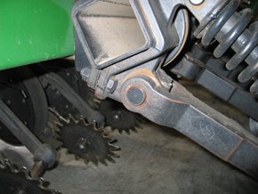
The flexible firming wheels are still the best choice because they can flex sideways up to 0.5-inch or more while remaining fully functional (See photo; if you are on perfectly level, square fields and running sub-inch guidance and auto-steer, perhaps it’s not an issue – for everyone else, it is.) The DuraLok stays cleaner than other designs, both for mud and vines or straw, since it has a lot of clearance between the hub and the firming arm, and no exposed bolts and nuts in the hub area. The urethane material of the DuraLok has exceptionally good wear-life (far better than the soft rubber on the other seed-lock wheels), and along with the narrow design, will go thru more mud than any other design.
You cannot afford to compromise on the seed-firming function – it is too crucial. Narrow firming devices are vastly superior for reaching the bottom of the ‘v,’ which is critical to their function, and also shed mud better. Run maximum pressure on them in the majority of conditions.
Strive to gently close the furrow, consistently breaking the sidewall and filling the furrow with loose material. Loose soil over the seed will slow the drying of the seed zone more than packed soil over the seed.
Air Velocity
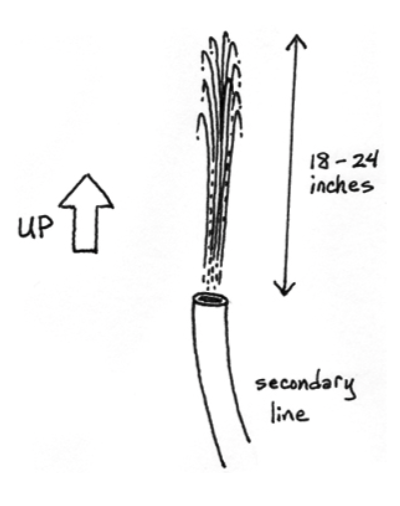
On air drills, beware too much velocity on the seed caused by excessive air pressure. To assess your air velocity, take one of the secondary lines off of an opener and aim it straight up in the air with some wire or tape. Run at normal speed, pushing a normal amount of product (seed + fertilizer). The product should be blowing about 18 – 24 inches out of the line. If it is blowing 5 ft up in the air, you have far too much air pressure. If you still have problems, take a look at air diffusers such as the centralized SeedVU from Exapta, or the secondary line “air brake” diffusers sold AirGuard (cyclone type) and by Dutch Industries (steel mesh) or Needham Ag. You can get the steel mesh ones without the internal deflector, which is advisable—it causes too much seed damage for peas, beans, etc. And, even with air diffusers, it is highly advisable to set the fan speed using the guideline set forth here, and to run our Ninja flaps on the boots. Indeed, going to the Ninja flap should be the first order of business, and if everything is adjusted correctly but placement is still inadequate, then start looking at air diffusers.
On the 1850 only, please note that the first year (’95) of manufacture, these air drills had the frame/rockshaft too high for the openers to function properly (can’t get much down-pressure, opener runs on its ‘heel’), which required a ‘drop-kit’ to remedy. If you are unsure whether your 1850 drill has the drop-kit already installed, look at the position of the rockshaft in relation to the frame and compare to 60- and 90-series air drills (See photo, and caption).
On the 90-series (or 60-series drills with 90-series boots) only, the firming wheel runs 0.75″ closer to the back of the seed boot, due to the redesigns previously discussed. When drilling over terraces or other uneven terrain where some openers momentarily come out of the soil, the firming wheel brakes on the boot, causing wear on both items and some instances of breakage of the rear edge of Extended Wear boots. The solution is to drill a new hole in the firming wheel arm, between the existing hole and the end of the strap (or replace the strap entirely with one 0.75 inch longer and holes 0.75 inch farther apart).
*No, we’re not John Deere fanatics – but these drills do perform reasonably well over a range of soil conditions and crops. We’d love to see something better come onto the market.
The first year the JD 1850 drills were built, the rockshaft ‘hangers’ caused the rockshaft to be too high, so the openers couldn’t develop much down-pressure. For a few years afterwards, Deere had a ‘drop kit’ upgrade with different hangers to lower the rockshafts to where they were on the 750 drills. The drop kit is no longer available per se, but all the parts can still be purchased thru Deere. It will set you back $8,000+. However, there’s another way: Flip your 1850 hangers upside down. This will lower the rockshaft a bit more than 3 inches, just a wee bit more than the OEM replacement hangers. The price is right, and it’s very important that this be done if you want the drill to work properly.